Rifts in Spreading Wax Layers

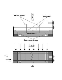
We are studying the structure and dynamics of rifts between two freezing wax plates floating on the melt and driven apart with constant velocity. A schematic of our experimental setup is given in the figure to the right.
The inspiration for the our experiments came from geophysics, where paraffin wax experiments have been used as a model for the mid-ocean ridges [1][2][3].The structure of the mid ocean ridges is characterized by faults (the so called transform faults), which are parallel to the direction of the plates' movement. In the experiment by Oldenburg and Brune [1] the molten wax was frozen at the surface by a flow of cold air. Then the solid crust was pulled apart with constant velocity and a rift was formed separating the crust into two solid plates. Their experimental setup is shown below.


They observed that a straight rift, initially perpendicular to the pulling direction evolved into a pattern consisting of straight segments interrupted by faults parallel to the pulling direction.
The following two pictures are scanned from their paper in Science [1].

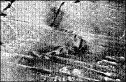

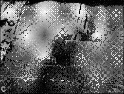
In the pictures the wax layer was pulled apart horizontally with a speed of roughly 1 mm/sec. For visualization the wax was dyed and illuminated from above with a lamp. Photographic pictures were taken of the surface. The main dark rift which is interupted by perpendicular faults is clearly visible. This pattern appears to be very similar to the one observed at the mid ocean ridges.
Motivated by this investigation and by conversations with Bruce Shaw, we have investigated the phase diagram in more detail, i.e., we investigated the rift structure as a function of the pulling speed. Although we used the same wax (Shell Wax 120) and the same conditions, we couldn't reproduce the "transform fault" pattern shown above. Instead we found a zigzag rift pattern. The movies below show the evolution from a flat rift to zigzags as a function of increasing spreading rates. Recently , thanks to Sarah Tebbens, we discovered that a similar zigzag pattern can also be observed in the dynamical rift formation processes of lava lakes.
The question remained why we saw the zigzag's and not transfrom faults. Well, it appears that SH120 has changed its properties over the past 25 years. According to Shell SH120 is made of crude oil. With some oil wells drying up the crude oil for the wax production process had to be changed. This led to a change in the crystallinity properties, i.e., SH120 was getting progressively less crystalline and such less brittle. As we have shown recently the synthetic Callista 158 is more brittle and shows transform faults. However, it does not show zigzag rifts.
Please click on the pictures below for an mpeg movie - be aware - this might take a while to download!


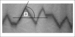
In the zig-zag we were able to describe the angle of the interface with respect to spreading direction by a simple geometrical model. It assumes that the problem is dominated by only two velocities, the externally given spreading rate (pulling speed) and the internally selected maximal growth velocity of the solidifying fronts. When the spreading rate exceeds the solidification speed the interface has to grow at an angle to keep up. The experimental data on the angles agrees well with this model. By the way, this is very similar to Mach's cone , i.e., to the shape of the wavefront of sound behind a supersonic airplane.

You can find a more detailed description of our observations in our publication.
The above argument describing the angle is so simple that it should be quite universal.


Indeed similar behavior was found by Bechoefer et al.[4] in his investigation of directional solidification of nematic liquid crystals. In directional solidification a material is dragged through a temperature gradient such that the material is molten on the hot side and crystalline on the cold side. The solid/liquid interface tries to keep up with the imposed velocity.Above a certain speed the so called Mullins Sekerka instability sets in. This instability lead to a sinusoidal modulation of the interface which is visible at the bottom of the figure.
Here, however, the transition was not from liquid to solid, but from a liquid to a nematic liquid.
A nematic liquid crystal (LC) has orientational but no translational order. In the experiment the surfaces of the top and bottom plates were treated in such a way that the LC aligned perpendicular to the top and bottom surfaces. However, the LC also liked to be perpendicular to the solidifying interface leading to regions where the LC was oriented parallel to the glas plates. As a result disclination lines were formed behind the solidification front sparating parallel from perpendicular alignment.
The different regions are visible as dark and bright under observation with polarized light. Bechoefer et al. observed that the disclination lines were triangular. They found that the angle could be described by the same argument given above. Here, the two velocities are the disclination velocity and the "dragging" speed.
References
[1] D. W. Oldenburg and J. N. Brune, Science 178, 301 (1972).
[2] D. W. Oldenburg and J. N. Brune, J. Geophys. Res. 80, 2575 (1975).
[3] J.W. O'Bryan, R. Cohen, and W.N. Gilliard, Geophys. Soc. of A. Bull. 86, 793 (1975).
[4] J. Bechhoefer, thesis, University of Chicago, 1988. P. Oswald, J. Bechhoefer, and A. Libchaber, Phys. Rev. Lett. 58, 2318 (1987).
For a more complete presentation, we refer you to our publication. We appreciate your comments!
The experimental research was conducted at the Laboratory for Atomic and Solid State Physics at Cornell University, Ithaca, N.Y., and was supported by THE ALFRED P. SLOAN FOUNDATION and THE US FEDERAL GOVERNMENT through the Material Science Center at Cornell.