Localization Phenomena and Dynamics of Brittle and Granular Systems
Rifts in Spreading Wax Layers: An Analogy to the Mid-Ocean Rift Formation?
Eberhard Bodenschatz, Nathan Gemelke, Jeron Carr, and Rolf Ragnarsson
Laboratory of Atomic and Solid State Physics, Cornell University, Ithaca, USA
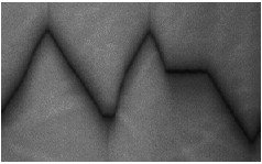
We are studying the structure and dynamics of rifts between two freezing wax plates floating on the melt and driven apart with constant velocity. The inspiration for the experiment comes from geophysics, where paraffin wax experiments have been used as a model for the mid-ocean ridges[1][2][3]. The structure of the mid ocean ridges is characterized by faults, which are parallel to the direction of the plates' movement. A good summary of the geophysical questions are given in the book by Keary and Vine [4]. We also recommend this website for further info on this topic.
In the original experiment by Oldenburg and Brune [1], the molten wax was frozen at the surface by a flow of cold air. Then the solid crust was pulled apart with constant velocity and a rift was formed separating the crust into two solid plates. They observed that a straight rift, initially perpendicular to the pulling direction evolved into a pattern consisting of straight segments interrupted by faults parallel to the pulling direction. The observed pattern was interpreted to resemble the transform faults of the mid-ocean ridges, and a model based on shrinkage and the mechanical properties of the wax was proposed [2].
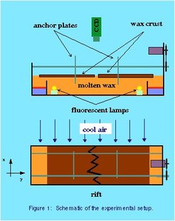
The experimental setup, which is identical to the one used earlier [5] , is shown schematically in Fig. 1. It consisted of a rectangular tray of dimensions 114x36x10 cm^3 with stainless steel side walls and an aluminum bottom. It was filled to a height of 8 cm with wax. The bottom was heated by a regulated circulating water bath to temperatures slightly above the melting range of the wax. To solidify the wax surface, cooled air was blown across the long side of the apparatus. Two vertical stainless steel anchor plates of 3 mm thickness were frozen into the wax. A micro-stepping motor was used to move the two anchor plates apart, each at the same speed, ranging from 1 microm/sec to 1 mm/sec. To avoid a buildup of solid wax at the ends of the tray, each wax crust was melted off in warmer regions of lateral size 10x20 cm^2. Each region was heated by an electric film heater mounted on an aluminum plate of size 100 x 200 x 3mm^3 and insulated from the temperature controlled bottom by a layer of 3 cm thick polyurethane foam. To minimize thermal cross-talk, two 6 cm high stainless steel plates separated the warmer regions from the main part of the tray, allowing the solid crust to pass over. The wax layer was illuminated from below by two fluorescent lamps placed into the molten wax and extending over the width of the tray, allowing the rift to be visualized from above with a CCD camera connected to a digital image processing system. We also illuminated the layer from above to image the topography of the wax surface with the same video system.
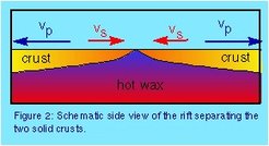
A schematic of the experimental situation as viewed from the side is shown in Fig. 2. The two solid plates are moved apart with constant pulling speed Vp and new material is solidified with velocity Vs in the rift between two solid plates. We have investigated two different waxes: Shellwax 120 [5] and Shellwax Callista 158. Both waxes shrink by about 10% when freezing. Shellwax 120 freezes at 54 degree C and has a solid to solid phase transition at approx. 35 degree C, which coincides with a change in the mechanical properties from plastic and easily deformable to brittle and hard. In contrast, Shellwax Callista 158 freezes at approx. 72 degree C and forms on freezing a brittle and hard material. Although, Oldenburg and Brune's[1] experiment with Shellwax 120 showed similar behavior to the mid-ocean ridges, we were not able to reproduce their findings using the "same" wax [5]. Instead of the transform fault pattern fromation we found the developent of a zigzag rift pattern. We were able to explain the results by a competion between the pulling and solidification velocities -- we used an argument which is very similar to that for Mach's cone , i.e., to the shape of the wavefront of sound behind a supersonic airplane. Our results of the investigation with Shellwax 120 are summarized in the letter [5] and on the webpage. One explanation for the difference in Oldenburg and Brune's and our observations is the change of the material properties of Shell Wax 120 over the past 20 years [6].
In the following we restrict our report to the observations with Shellwax 158. In the experiment the molten wax temperature was regulated to (77+-0.5)degree C and the wax was cooled from above by air with a temperature of (20.5+-0.5) degree C. Shellwax Callista is a synthetic wax and promises to have reproducable physical properties [6]. One of the important properties of SH158 that its is very brittle once solidified.
Our experiments show many similarities with the morphological instabilties in the mid-ocean ridges. We did not find the zigzag pattern we observed for SH120 [5]. Contrary to SH120, here the interesting behavior appears at slow speeds ( Vp < 100 microm/sec) where the rift was frozen over, suggesting brittle fracture as the dominant mechanism at the rift axis.
- For slow speeds (< 20 microm/sec) we observed that the rift remained straight. In the pulling direction, the topography showed a deep valley (1-5 mm) with its lowest point at the rift axis.
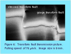
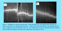
- For medium speeds of 20 microm/sec < Vp < 35 microm/sec the large scale structure of the rift remained flat interrupted by stressed transform faults. This is shown in Fig. 3A. Figure 3A also shows small dark areas which correspond to roll up regions very similar to overlapping spreading centers (OSCs). In the pulling direction, the topography showed a shallow valley (0-1mm) with its lowest point at the rift axis. An mpg movie of this regime is available here ( 1.03MB). The wax layer was imaged from above in reflection at an angle of approximately 30 degrees. The depth of the image is 91 mm, while the spacing between frames is 10 seconds. The pulling speed is 35 micron/sec.
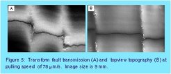
- For fast speeds of 35 microm/sec < Vp < 100 microm/sec the pattern is dominated by transform faults and fracture zones. A typical transmission picture is shown in Figure 3B. The fracture zones show a shallow depression (1mm depth) and have the appearance of gouges. Only few stressed tranform faults/fracture zones are found where the solid crust appears to be pushed together. In the pulling direction, the topography showed a shallow ridge(0-2mm) with its highest point at the rift axis. An mpeg movie of this regime is available here (1.08 MB) . The wax layer was imaged, as in the previous movie, from above at an angle of approximately 30 degrees. When following the fracture zones the rise in height at the rift is apparent. The depth of the image is 91mm, while the spacing between frames is 10 seconds. The pulling speed is 75 microns/sec.
- For speeds Vp > 100 microm/sec the rift widened and was not frozen over. Only a straight rift was observed.
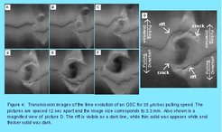
As discussed above, at medium speeds we observed structures resembling that of Overlapping Spreading Centers (OSC). OSCs are relatively common structures, reported both in wax [7] and the geomorphology of the earth [8,9]. Figure 4 shows a transmission picture of the stages in the development of an OSC. The rift is visible as a dark line and the brightness is a measure of the thickness of the wax. The evolution started from two offsetted rift segments as shown in Fig.4A. Between the rift segments a solid piece of wax rotated and grew both in width and height by accretion and by cracks propagating into the previously formed solid wax (see also Fig.4D). The lower crack's tip propagated to the left, first down, then up. The position of the upper crack's tip remained approximately fixed, indicating that it propagated into the crust, which had been formed at the lower rift, with a speed equal to the pulling velocity. During the rollup, material predominantly raised in a spiral shaped elevation (dark in Fig.4). After 48sec the part of the upper rift which is above the S-shapped accretion disk disconneted (Fig. 4D) and moved rigidly with the upper plate. Two new OSCs fromed at both corners of the newly etablished rift.
