header

Variable Density Turbulence Tunnel

Present configuration and existing infrastructure:

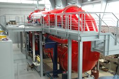
The Variable Density Turbulence Tunnel (VDTT), seen on the right, is a wind tunnel that circulates pressurized gases.  Working fluids are air, sulfur hexafluoride (SF6), or other noncorrosive gases.  Reynolds numbers of up to Rλ~1700 can be reached with SF6 at 15bar.  The tunnel is upright and consists of two measurement sections each with a cross-sectional area of 1.7m2 and lengths of 9m and 7m.  The cross sections are approximately octagonal, as can be seen in the picture below.  The mean flow speed can be set to between 0.5 and 5m/s.  The tunnel is pressure and temperature controlled, and has optical and electrical interfaces.  The pressure can be adjusted to between 1mbar and 15bar.  The circulating gas can be filtered to <1μm. 

Passive grids are mounted at the upstream end of the measurement section to generate turbulence.  Three grids can be installed with 53.3mm, 106.6mm, or 186.6mm grid spacing.  These are biplanar grids of bars with square cross section that block 40% of the cross section.  The integral scales of the flow are approximately equal to the grid spacing, and the turbulence intensities are 2-3%.

A linear traverse with a cable-chain can move probes up and down the length of the tunnel.  The traverse is shown in the picture above.  Since the picture was taken, the traverse has been extended so that it can approach to within 1m of the grid.  Transit time from one end of the measurement section to the other is about 20 minutes.  We also have linear traverses that can move probes across the test section in both directions at a fixed distance from the grid.  We use a Dantec anemometry system in combination with Pitot-static tubes for calibration of the hot wires. 

Possible constraints on experiments:

During pressurized experiments, the only communication with the inside of the tunnel is through electrical feedthroughs.  Optical fiber feedthroughs are also possible.  We typically monitor the status of various devices with web cameras, accelerometers, and temperature sensors.  Cameras should be housed in sealed enclosures that contain air at 1bar.  This is because the optical index of SF6 changes sufficiently as the pressure increases to prevent the cameras from focusing.  On the other hand, our experience is that electronic devices typically work under pressure, without need to protect them.  
There is limited space between the outer pressure vessel wall and the inner walls of the wind tunnel itself to mount equipment.  This space has a complicated geometry, but roughly a device must be thinner than 10cm and have a width less than 40cm in order to fit in these spaces.  
There is also limited space to work in the tunnel.  Devices must be able to fit in through the 80cm manhole, and be installed by a person who is sitting or bent over.  The height of the tunnel is about 1.2m.  
It may be useful to bear in mind that the smallest scales of the flow at the highest Reynolds numbers are about 10mm.  The aerodynamic loads due to the wind can also be substantial, since the density of SF6 at 15 bar is about 107kg/m3, about one tenth of water and one hundred times larger than air.  


Go to Editor View